PO Composite Debug Headset Display Controller
[b]Tired of not knowing what's going on in every last logic node of that controller you're building? Want to see all your data at the same time, without having to look at multiple dials one after another? Need same-tick readings? Can't figure out how to fit that debug screen into your fighter cockpit? Phebus Overengineering NLC got you covered! Get all your numbers and boolean states right onto your headset with this debug display controller.[/b]
Overview
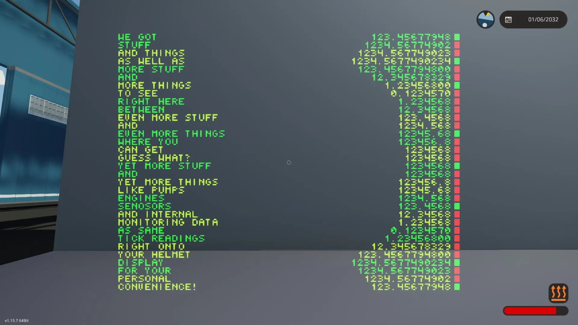
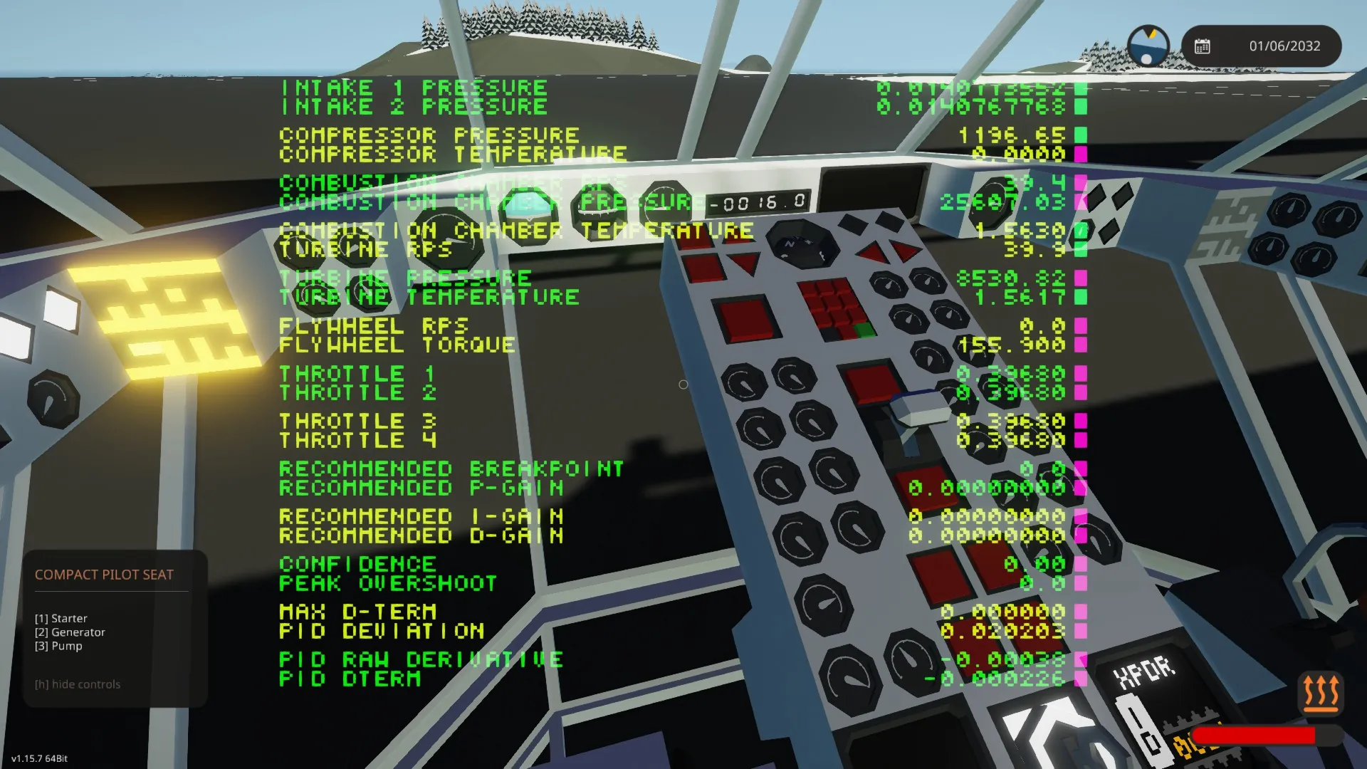
This is a [b]general-purpose composite signal debugger and data monitoring system[/b] designed for use with high vertical resolution [b]displays of headsets/helmets[/b], but it also works on monitors/scopes as far as resolution allows.
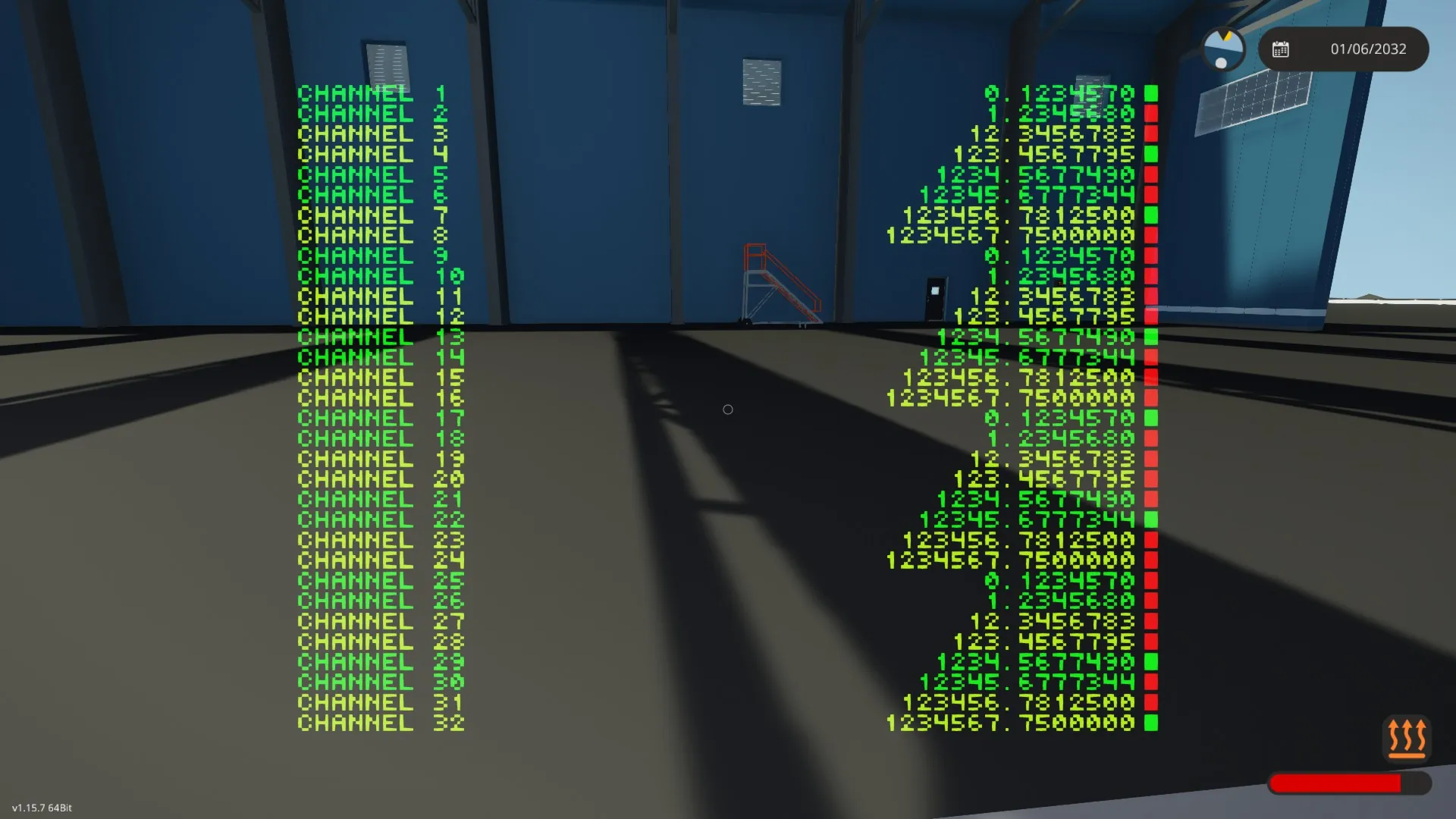
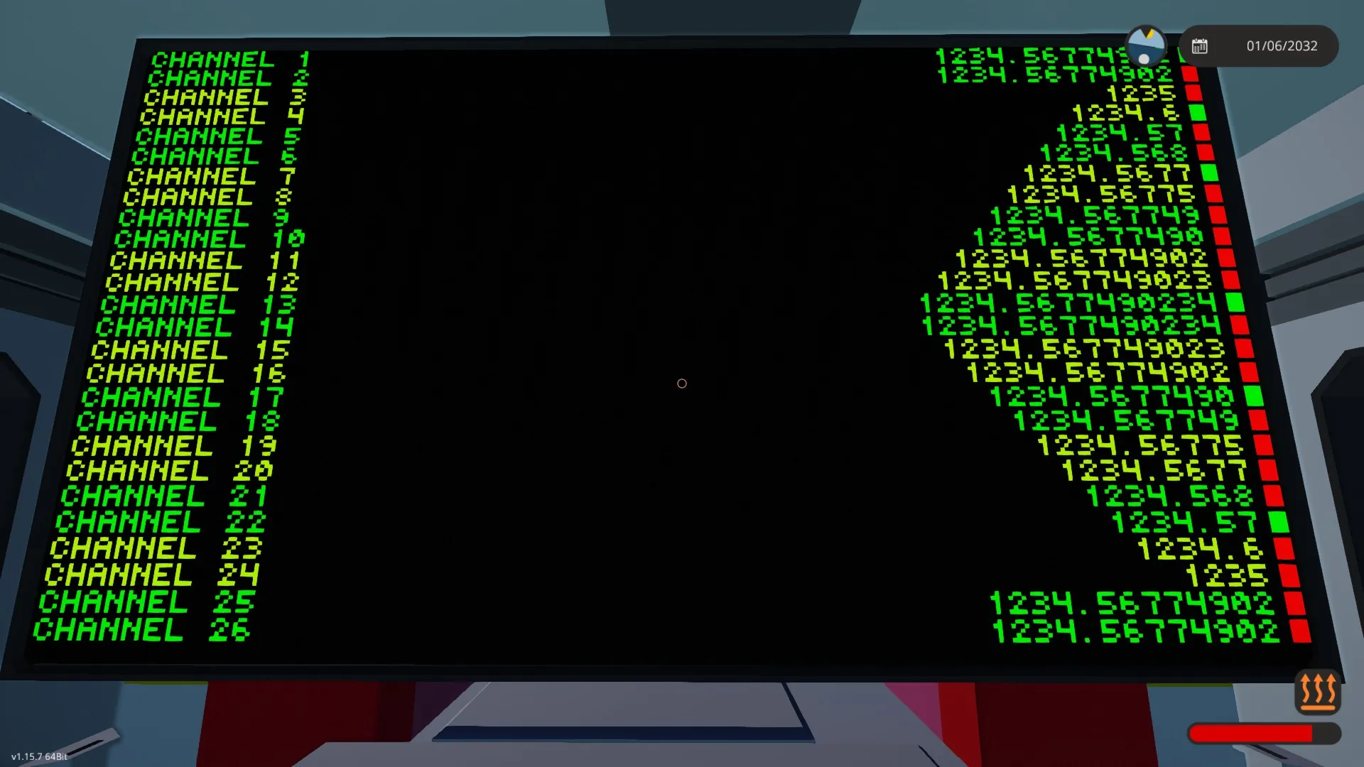
- Displays [b]up to 32 composite channels[/b]
- Shows [b]numbers and boolean states simultaneously[/b]
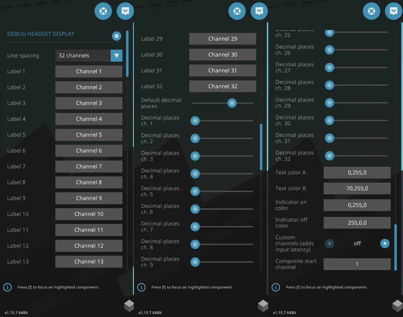
- Fully configurable via property tab:
- Per-channel control over:
- Labels
- Decimal precision
- Color palette
- Optional line spacing modes for improved readability when limited channels are used
- Optional [b]channel remapping system[/b] for skipping channels
Quick setup guide
1. [b]Place the controller[/b]
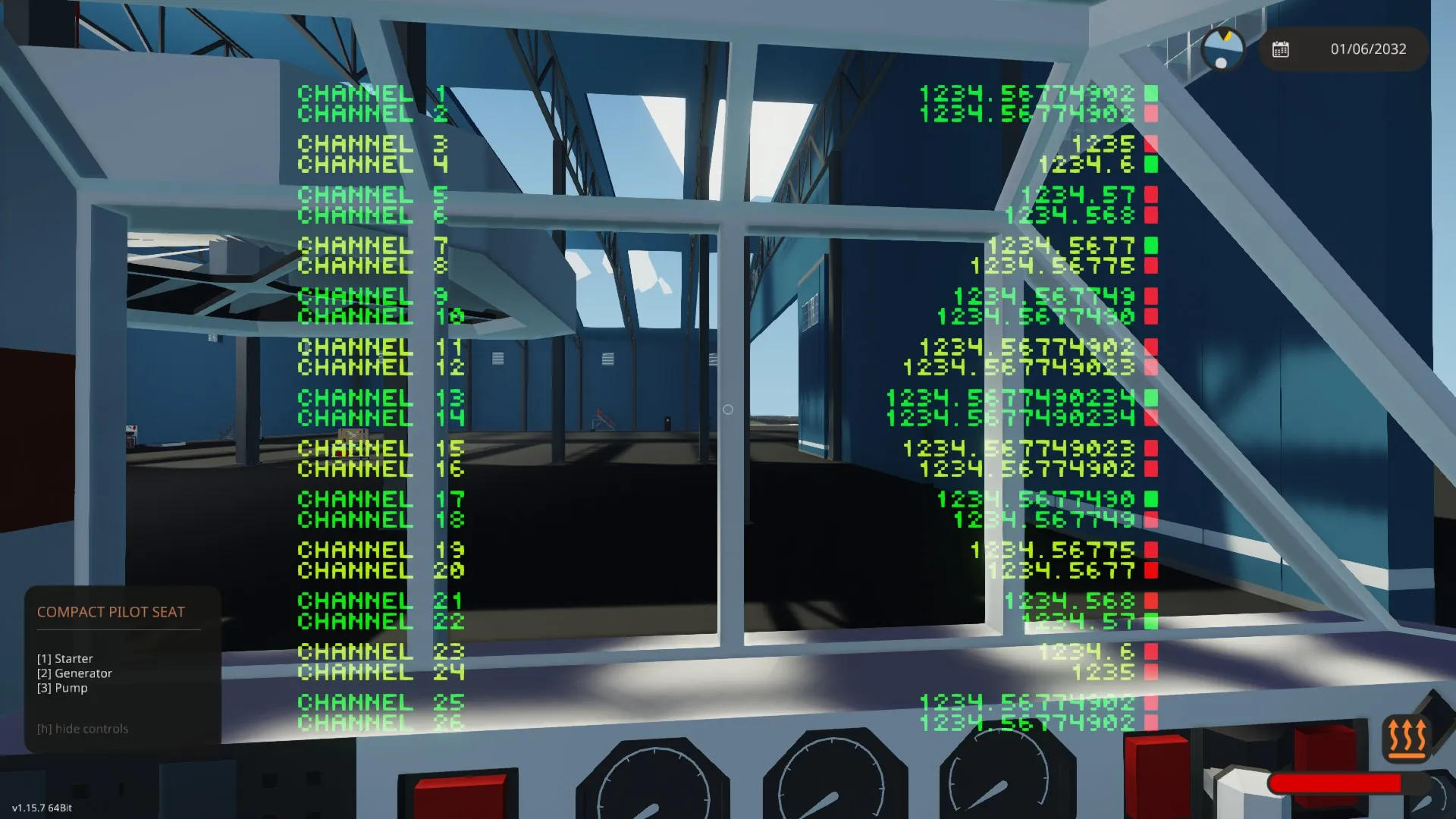
2. [b]Connect a display:[/b] ideally a pilot/driver seat, helm, etc.; monitors work as well, but with limits.
3. [b]Connect a composite signal[/b] to the controller’s composite input.
That’s it — the display is ready to use. But if you like, you can:
4. Open the [b]property tab[/b] and configure:
- Labels for the channels you want to display
- Decimal precision as needed
- The color palette
- Line spacing
5. Display a limited amount of channels, by clearing the label for the first unused channel.
6. Enable “Custom channels” to remap the incoming signal. You can then define a different start channel to skip incoming channels.
How the controller works
Composite signal handling
By default, the controller reads all 32 channels directly from the incoming composite signal and displays them one-to-one.
An optional [b]remapping system[/b] is included for more advanced use cases:
- Composite read blocks extract channels starting from a configurable base channel
- These values are written into a new composite signal
- A switchbox swaps between both signals
This allows users to:
- Skip unused channels at the beginning of a composite line to realign signals
- Inject additional external inputs into the debug display if desired (requires adding input nodes)
As this system introduces additional read/write steps, it adds input latency.
Display logic
Each displayed line consists of:
1. A label on the left
2. A right-aligned numeric value
3. A boolean indicator box on the far right
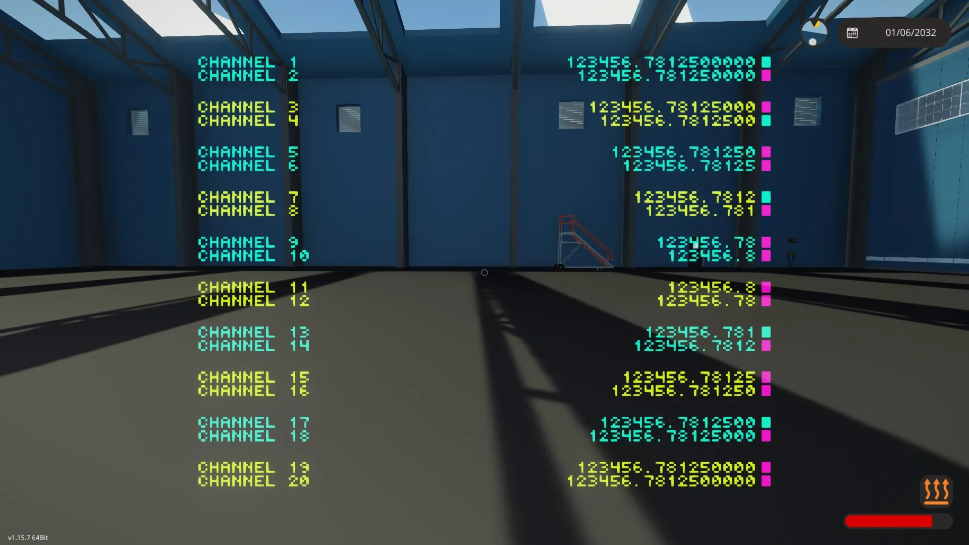
Lines are grouped into pairs, allowing alternating text colors for readability.
When not all channels are used, optional spacing modes can insert extra vertical spacing between line pairs to improve readability even further.
Channel count control via labels
The number of displayed channels is controlled entirely by the labels:
- Labels are read in ascending numerical order starting from Label 1
- Once the system finds an empty label, it stops processing them
- All subsequent labels are ignored
- The system only displays as many lines as it found labels
This allows you to display [b]only the channels you need[/b], avoiding visual clutter when monitoring your data.
Customization guide
Below is a complete explanation of every property option found in the property tab.
Line spacing
Options:
- “32 channels” → No extra spacing (maximum density)
- “26 channels” → Moderate spacing between channel pairs
- “20 channels” → Large spacing between channel pairs (best readability)
This only affects vertical spacing and not the actual amount of channels displayed. The mode names are based on the amount of lines that fit on a headset display.
Label X
Defines the text label for channels 1 to 32.
- Labels must be filled [b]contiguously[/b], starting from Label 1
- The first empty label field stops further channels from being displayed
Default decimal places
Defines the default amount of decimal places used for numeric values.
Decimal places ch. X
Overrides the decimal precision for a specific channel.
- “-1” → Use the default decimal setting
- “0–10” → Use that exact amount of decimal places
Text color A/B
Primary and secondry text color (used for alternating line pairs).
Valid color formats (for all color fields): RGB values (3 numbers from 0 to 255, separated by a single comma each), like this:
R,G,B
Indicator on/off color
Colors used for the boolean indicators.
Custom channels
Enables the composite remapping system.
- Off → Direct composite passthrough (lowest latency)
- On → Uses remapped composite channels
Only enable this if you need channel skipping or custom routing. It adds a couple ticks of input latency, due to the additional logic blocks required.
Composite start channel
Defines the first composite channel read by the remapping system.
Example: Start channel = 5 means display channel 1 shows composite channel 5.
Only relevant when Custom channels is enabled.
Known Limitations
Fixed font size
This controller uses the vanilla Stormworks font. As a result:
- Rotated screen orientations are not supported
- Line height is fixed
- Maximum channel count is limited by vertical resolution
- Horizontal space must be managed via label and number length
Vertical resolution is the limiting factor
Only helmet/headset displays have enough vertical resolution to show all 32 channels.
Available line counts for other displays:
- 9x5/scope: 26 lines
- 3 blocks tall: 16 lines
- 2 blocks tall: 10 lines
- 1 block tall: 5 lines
Mixed display widths are not supported
Connecting multiple displays with different screen widths to the same video output will cause horizontal misalignment.
Users are expected to connect:
- One display, or
- Multiple displays of the [b]same size[/b]
Custom channel routing adds latency
When “custom channels” is enabled:
- Composite signals pass through additional logic
- This introduces a minimal but measurable delay
This mode should only be used when channel re-mapping is required.
No dynamic layout adjustment
The controller does not dynamically scale or reflow content based on screen size.
Layout behavior is controlled exclusively via:
- Resolution of the display that is connected during initialization
- Line spacing mode
- Number length (determined by the order of magnitude and the decimal places setting)
Color parsing is strict
Color strings must be entered such that the values are speparated by commas: R,G,B.
Omitting a comma, or putting other characters (except spaces) in, will render the string invalid, and replaced by a fallback color (white).
Disclaimer
If you choose to mess with the internals of this controller, you'd better know what you are doing as there will not be support for issues that arise from this.
As an unregistered no liability company, Phebus Overengineering NLC bears no liability whatsoever, and can therefore not be held responsible for any damages (material, emotional, or any other kind) that may or may not result from using our products.
Regardless of that, we still think you might have fun using them. Maybe. Or not. We don't actually care. We just want to make ludicrously overengineered products, really.
License
[b]Do with this whatever the heck you want, but don't pretend you made it.[/b]
If you want to do me a favor, help make this tool more visible to other creators by subscribing, liking, and whatever else helps with that.