All Factorio power networks have optical fibers embedded which can be used to transfer red and green signals anywhere a power network is connected.
Fiber networks can transfer signals over very long distances. Each power network has a number of fiber strands and each strand can carry up to 16 different "fiber colors". Each color allows the transmission of a set of red and green signals.
This mod provides a new entity: The Fiber Optics Connector (FOC)
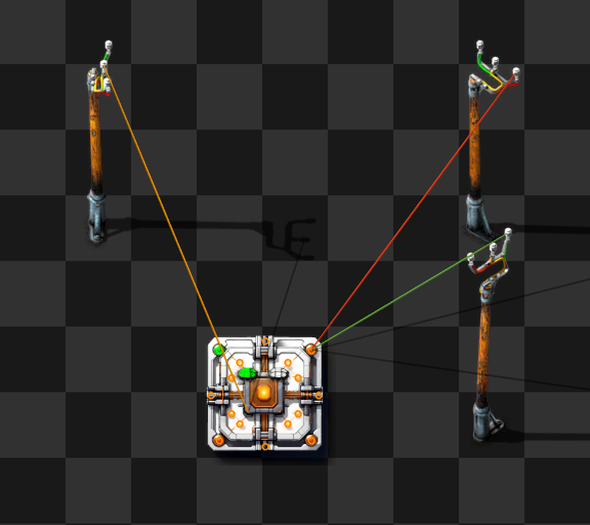
A Fiber Optics connector provides two sets of access points:
- up to 16 IO Pins for circuit signals. Each Pin fully supports bidirectional red and green signals
- two power pins to connect to power networks
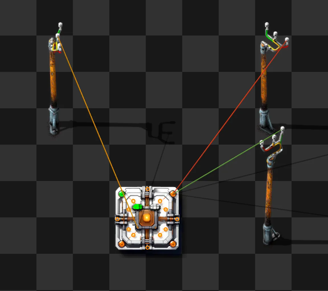
When a connector is powered up (it needs to be placed in a power coverage area) and connected to one or two power networks using copper cables, one or both indicator lights will light up (either red or green). This signals that the connector has established a link to the fiber optic cables and, if green, is ready to send and receive signals from other FOCs on the same power network.
Connecting to the same power network twice will only give one light. Connecting to two networks and then merging them will drop one of the lights.
It can take up to five seconds for the lights to turn on (or turn off when disconnected).
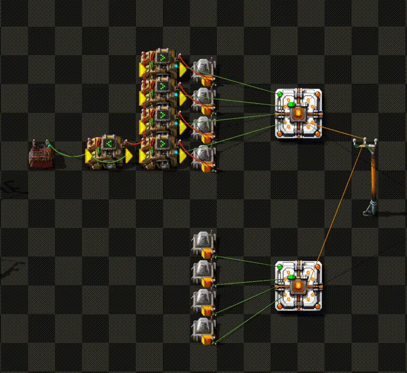
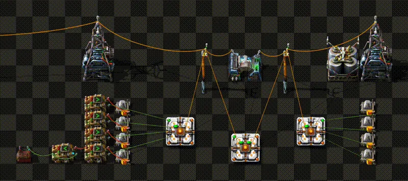
The power network does not need to be the same network that provides power to the Fiber Optics connector. It may even be preferential to provide power from the global power network but transfer signals across a smaller, isolated network:
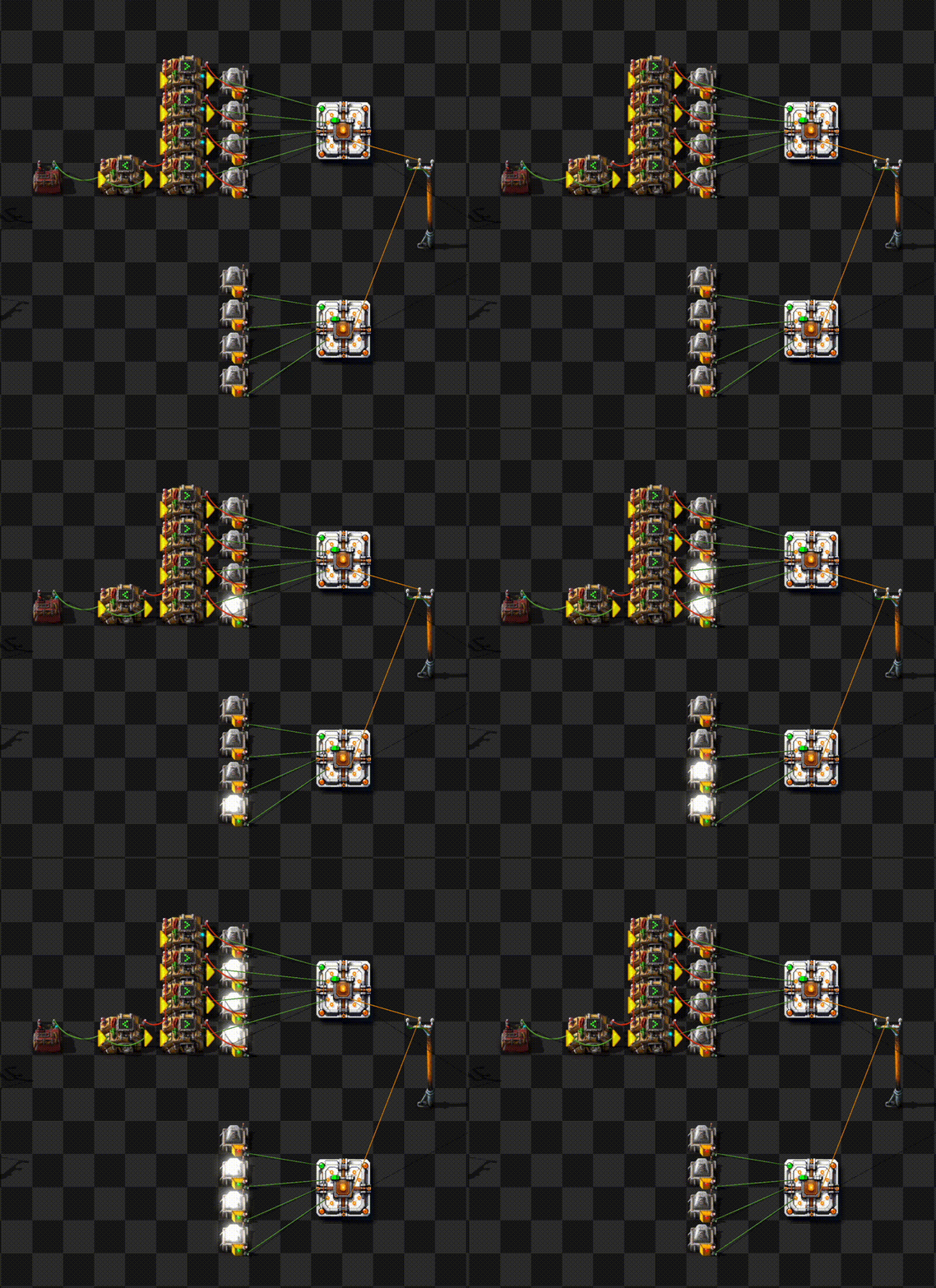
When connecting to multiple networks, the Fiber Optics Connector acts as a bidirectional bridge. Signals from one network will cross over to the other and vice versa.
Multiple fiber optics connectors form a bus across a power network. Each pin is fully connected to the same pin on all other FOCs. The current generation of FOCs can transfer up to 16 red and 16 green signals simultaneously across up to two power networks.
Fiber network properties
- Each power network (which is identified by its network number) connects all Fiber Optics connectors that use the same fiber bidirectional for red and green signals.
- A power network is per-surface and multiple networks can exist (networks that do not share a copper connection).
- Each power network has multiple fibers that are completely independent. By default, a Fiber Optics connector connects to the "default" strand that exists in every power network.
- Each fiber has separate colors for each I/O pin of the Fiber Optics connectors. Currently, all Fiber Optics connectors have 16 pins which are hard-coded to Fiber color 1-16.
- Each Fiber Optics connector can connect to one or two power networks. For technical reasons, it must connect to the same fiber strand on both networks.
When a connector is hooked up to a power network, it runs a negotiation protocol and when it successfully completes, it turns one of the status LEDs on. There are two status LEDs for up to two network connections.
Each LED signals that there is a connection to the fiber network. The color of the LED reflects the transceiver status (see below). Only when the LED is green, data is flowing.
GUI
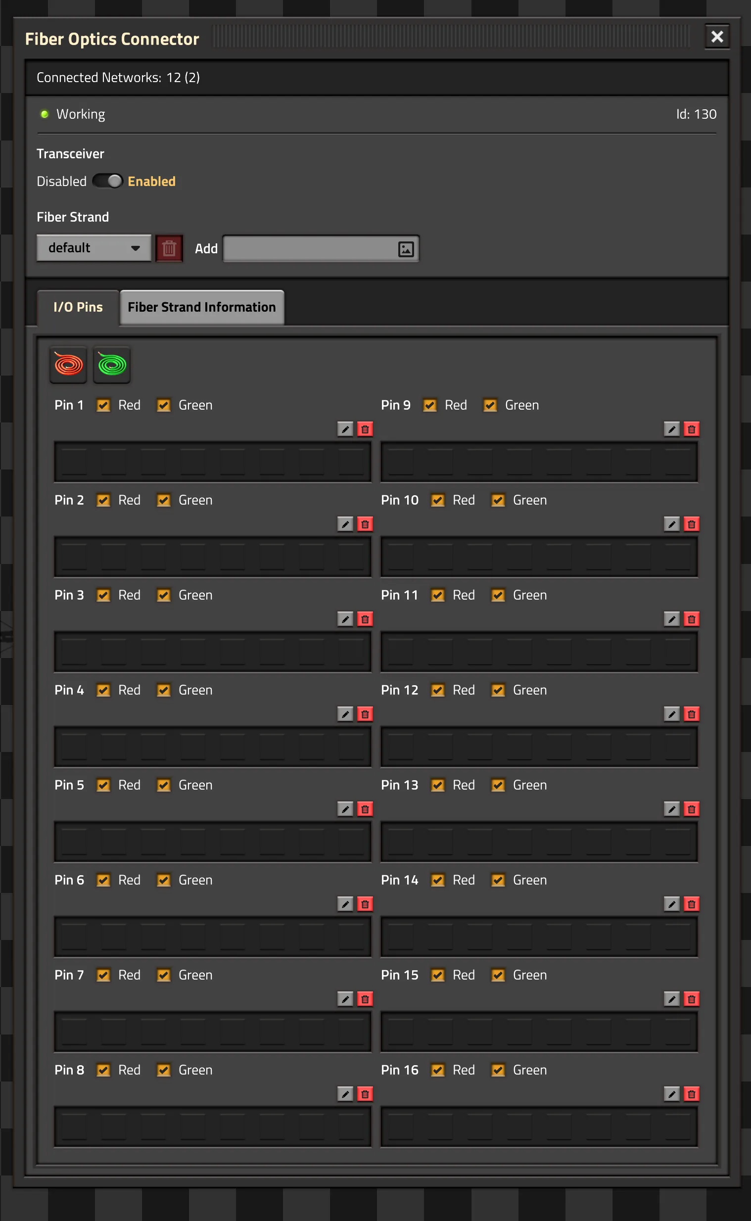
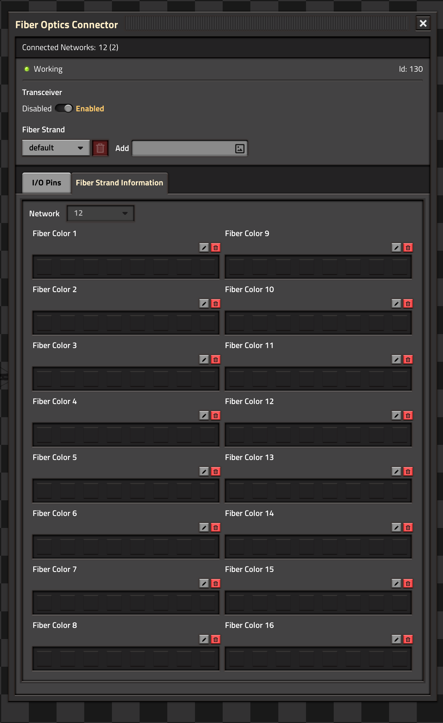
The Fiber Optics connector GUI opens when clicking on any of the I/O Pins. It contains a header and two panels:
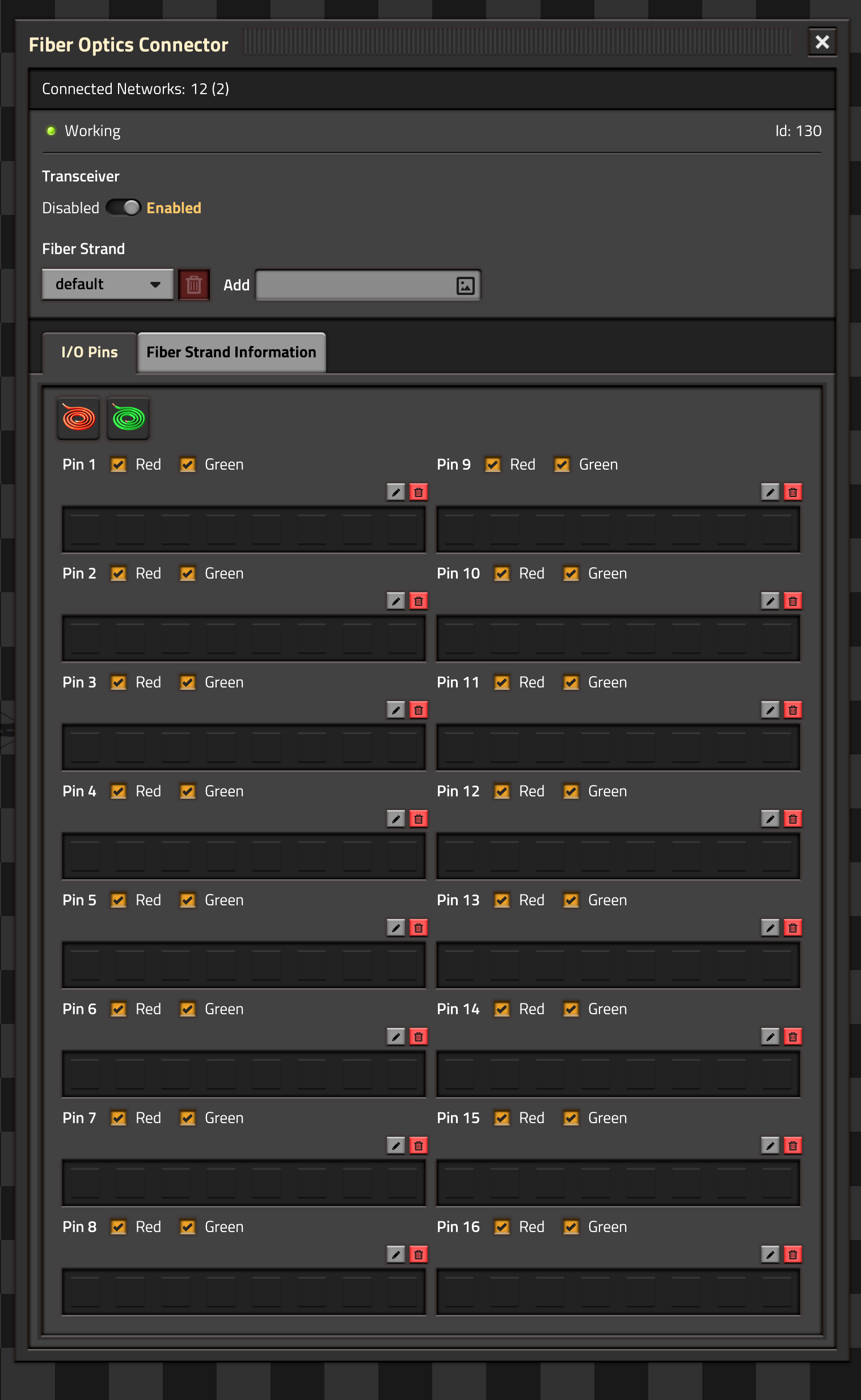
Status Header
The Connected Networks line displays the power networks that a Fiber Optics connector is connected to and how many connectors were detected on the network.

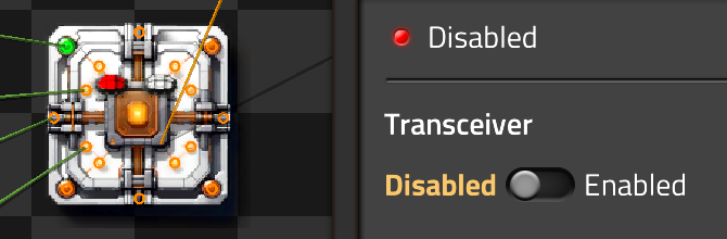
Transceiver controls whether the Fiber Optics connector exchanges data with the network. If the transceiver is turned off, the LEDs will turn red, if it is enabled, they are green.
The Fiber Strand menu controls which fiber strand is connected to the Fiber Optics connector. By default, the default strand is used. New strands can be named through the Add textbox and selected in the Drop-down:
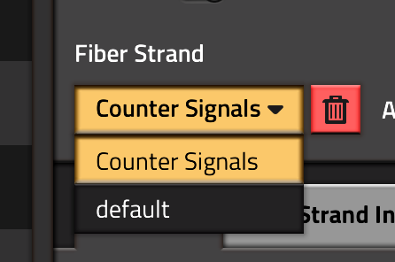
Fiber strands can be deleted (except the default strand). Any connector that was connected to a deleted strand will be reconnected to the default strand.
I/O Pin Panel
This panel displays the state of all I/O Pins on the Fiber Optics connector. For each Pin, the signals currently present on the Pin are displayed. This will work even if the connector is in low power or no power mode or if the transceiver is disabled. In this case, only the signals on the Pins are shown. If the connector is powered and the transceiver is enabled, it will also show the signals on the network.
Each pin can select whether red, green or both signals are connected to the fiber network. The wire symbols on top can toggle all red or all green wires.
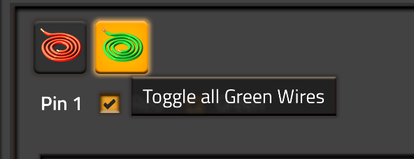
For each pin, a description can be added (see below).
Fiber Strand Panel
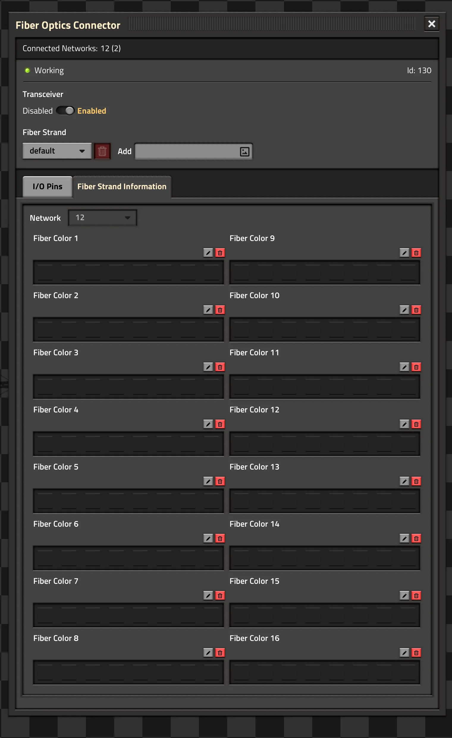
The network selector drop-box is only available if two networks are connected to the Fiber Optics connector. Such a connector acts as a bidirectional bridge and will carry all signals from one network to the other.
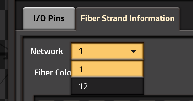
Similar to the I/O Pin panel, this displays the signal status of the different Fiber colors on the selected Fiber strand. For each color, the signals currently present in the network are displayed. Similar to the I/O Pins, this will always display the network signals. Signals from the local I/O Pins will only be shown if the transceiver is enabled and sufficient power is available.
Fiber colors always carry red and green signals.
Each Fiber color can also have a description. Those descriptions exist only as long as the fiber network exists. If a power network is dissolved (by removing the last power pole from it), the descriptions are deleted. The network drop-down selects which network descriptions are edited.
Network and I/O Pin descriptions
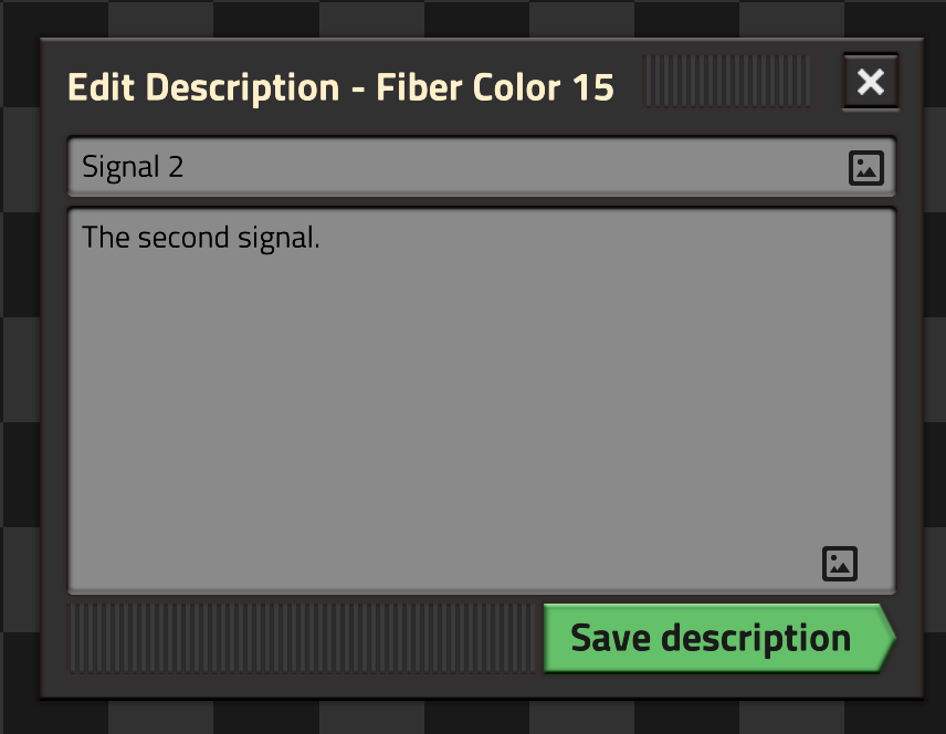
For each I/O Pin and Fiber color, a description can be added by clicking on the "pen" symbol next to the I/O Pin or Fiber color status box. It opens an edit panel for title and body.
Pin Hover Information
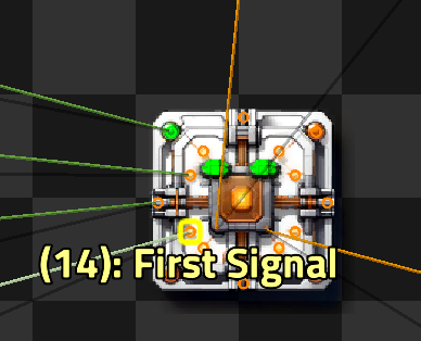
When hovering over an I/O Pin, it will display the following information:
If it is Red, the Red signal is connected, Green means the Green signal is connected. Yellow is both signals, white is no signals are connected.
The Pin number in braces is always shown. If a description is set (either on the Pin itself or the Fiber strand), it is shown as well.
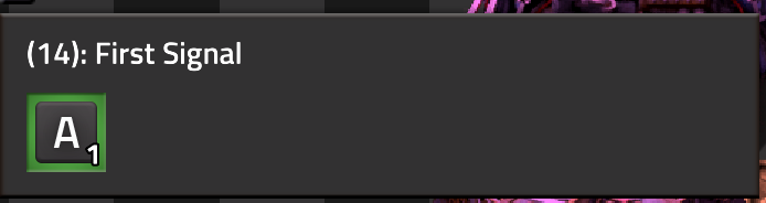
Lastly, while hovering an I/O Pin, a panel on the left side shows the currently present signals on that I/O Pin. This is the same information as on the I/O Pin tab in the main GUI.
Settings
Connector Refresh Interval (Startup, Default: 300)
How often each Fiber connector is checked for new or changed power connections. This is the delay between connecting a power network and the LED turning red or green. Setting this to very low values will affect FPS. The default (300 ticks = 5 seconds) is a good compromise even for many connectors.
Network Refresh Interval (Startup, Default: 60)
How often each power network is checked for removed or invalid connectors. This is internal housekeeping and debugging only. Settings this to low values will affect FPS. The default (60 ticks = 1 second) should for almost any game.
Debugging Mode (Startup, Default: off)
Makes the fiber connection Hubs visible and draws wires from each connector to the hubs. Only turn on for debugging, preferably in a separate game to find problems.
Console Commands
/fiber-optics-resync-networks - Update all Fiber network connections
Rebuilds the Fiber network connections of all Fiber Optics connectors. Fixes any connector that has a "dangling" network connection or is not connected to a power network even though it has a copper connection. Rarely used, often for debugging or fixing some weird connector state.
/fiber-optics-prune-networks - Remove all fiber networks without corresponding power network
As mentioned above, as soon as a Fiber Optics connector is hooked up to a power network, the corresponding fibers are organized in a fiber network. This exists as long as there is at least one power pole representing that network. When the last power pole is removed, the power network is deleted and will never be reused. But the corresponding internal state for the fiber network is still stored. This is a small amount of data but it can compound over time, especially when many small networks are created and deleted. Running this command finds all fiber networks for whom no power network exists and deletes those.
This is not automated as finding all power networks is relatively expensive (for a medium sized surface it can take 80-100ms) and might lead to a short FPS drop when the command is run.
Blueprinting
A lot of code went into making Fiber Optics connectors as blueprintable as possible